The flow limiter inserted in this valve complies with the requirements of Standard UNE 60719. For correct operation, the valve must always be in the fully OPEN position. In intermediate positions, loses effectiveness.
Although the valve can work at a pressure of 0.5 Bar, the internal flow limiter must work without exception at the pressure indicated in the upper panel (20/150 at 37mbar and 1/2 ” at 21mbar). Never exceed these pressures for each one.
The nominal flow rate of each flow limiter (Q Nominal) is expressed in m3/h for each type of gas. For the valve of 20/150 it is expressed in m3/h of Propane (GPL) and for the valve of 1/2 ” it is expressed in m3/h of Natural Gas.
The tripping flows are within a range from 1,3 m3/h to 1,8 m3/h of propane (GPL) for the limiter of the 20/150 valve and from 2,0 m3/h to 2,9 m3/h of Natural Gas for the limiter of the 1/2 ” valve. Respect always the flow direction marked with the arrow.
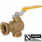
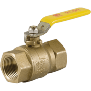
This valve can be installed in any existing installation, not requiring any type of modification on it, since the basic installation measures don’t change with respect to any other internal valve of DN10 without flow limiter. See dimensions L, H, K y el ØS.


COMPONENT MATERIAL
1 Bonnet Brass
2 Bonnet O-Ring NBR
3 Flow Limiter Different material
4 Ball Brass
5 Teflon Seat P.T.F.E.
6 Body Brass
7 Shaft Brass
8 Shaft O-Rings NBR
9 Shaft Nut Brass
10 Spring Stainless Steel
11 Handle Aluminium alloy
12 Screw Zinc plated steel
Code
7820147100
7820157100
Dimensions
M 20/150 x 20/150 M
M 1/2” x 1/2” M
DN
10
10
Pressure
37 mbar
21 mbar
QN
1,0 m3/h
1,6 m3/h
Type of gas
G.L.P.
Natural Gas
Flow limiter 1,5 m3/h
D
20.150
1/2”
ØD1
13,0±0,2
14,5±0,2
L
55±2,0
55±2,0
H
16±1
16±1
K
35±1
35±1
ØS
4,5±0,5
4,5±0,5